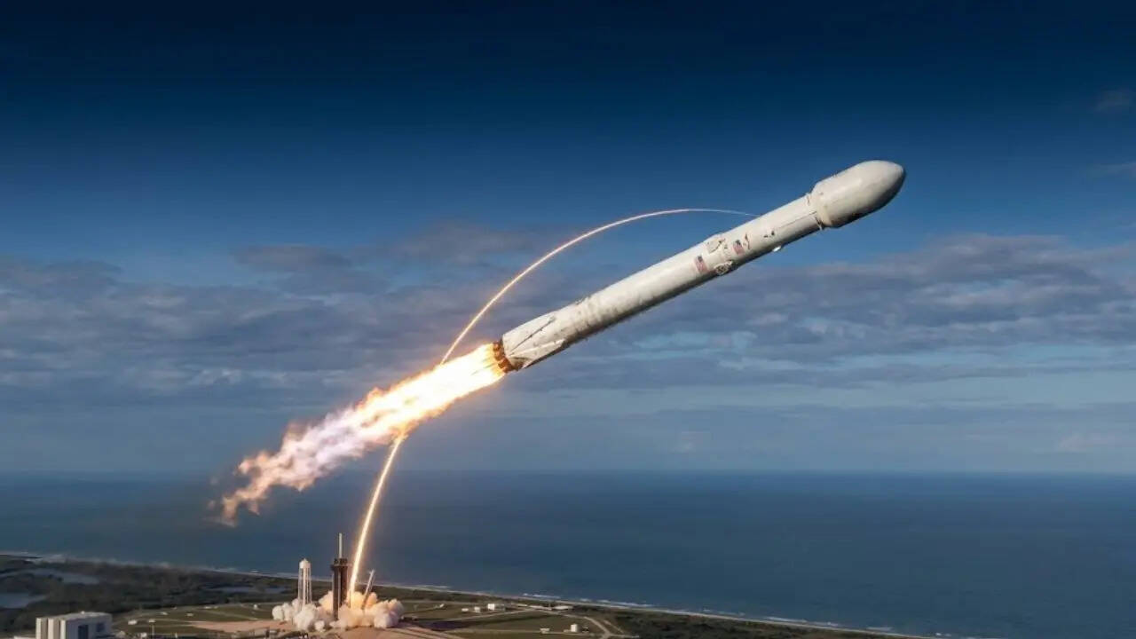
To understand why rockets execute a curved trajectory rather than a vertical ascent, one must analyze the physics of orbital mechanics and energy efficiency. The standard assumption posits that the curve is an aerodynamic choice or an attempt to avoid falling back to Earth. Instead, the trajectory is the mathematical minimization of two competing variables: gravity losses and aerodynamic drag. The ascent profile is an optimization problem balancing these two forces to reach the required orbital velocity of roughly 7.8 kilometers per second at the lowest possible propellant cost.
The Kinetic and Potential Energy Equations of Ascent
Reaching Low Earth Orbit (LEO) requires an enormous amount of kinetic and potential energy. The primary objective of a launch vehicle is not simply to reach high altitude, but to achieve a specific orbital speed. The specific orbital energy $E$ of a spacecraft in a circular orbit is given by:
$$E = -\frac{\mu}{2r}$$
Where $\mu$ is the standard gravitational parameter ($3.986 \times 10^5 \text{ km}^3/\text{s}^2$ for Earth) and $r$ is the distance from the center of the Earth. The total energy required includes both the potential energy to reach orbital altitude and the kinetic energy required for the orbital speed:
$$v_{\text{orbit}} = \sqrt{\frac{\mu}{r}}$$
For an orbit at an altitude of 200 kilometers, the required orbital velocity is approximately 7.78 km/s.
The mass required to achieve this velocity is governed by the Tsiolkovsky rocket equation:
$$\Delta v = I_{\text{sp}} g_0 \ln\left(\frac{m_0}{m_f}\right)$$
In this relationship, $I_{\text{sp}}$ represents the specific impulse, $g_0$ is the standard gravitational acceleration, $m_0$ is the initial mass (including propellant), and $m_f$ is the final mass (empty weight). The vehicle must alter its velocity vector by a magnitude of approximately 9.0 to 9.5 km/s to account for gravity and drag losses during ascent.
The Two Pillars of Ascent Losses
To optimize the trajectory, engineers must minimize the sum of two dominant loss factors: gravity losses and aerodynamic losses.
Gravity Losses
When a rocket points straight up, it works against gravity for a longer period. The velocity deficit caused by gravity is expressed as:
$$\Delta v_{\text{gravity}} = \int_0^t g(t) \sin(\theta) , dt$$
Where $\theta$ is the angle between the velocity vector and the horizontal plane. If a rocket ascends vertically ($\theta = 90^\circ$), $\sin(\theta) = 1$, and the gravity losses are maximized over the duration of the burn. By pitching the rocket away from the vertical direction, $\theta$ decreases, which reduces the value of $\sin(\theta)$ and minimizes the velocity lost to fighting gravity.
Aerodynamic Drag Losses
The force of aerodynamic drag $D$ on the vehicle is defined as:
$$D = \frac{1}{2} \rho v^2 C_d A$$
Where $\rho$ is the atmospheric density, $v$ is the velocity, $C_d$ is the drag coefficient, and $A$ is the cross-sectional area. The drag coefficient $C_d$ is not constant but varies with the Mach number:
$$C_d = C_d(M)$$
At transonic speeds (around Mach 0.8 to 1.2), the drag coefficient spikes due to wave drag. Balancing these two loss factors requires an S-shaped trajectory. If the rocket curves too early, the dynamic pressure on the vehicle increases significantly at lower altitudes where the air is dense, leading to prohibitive drag losses and structural failure due to aerodynamic loads. If it stays vertical for too long, the gravity losses consume too much propellant.
The Mechanics of Dynamic Pressure and Max Q
The maximum dynamic pressure, commonly known as Max Q, represents the peak aerodynamic load experienced by the rocket during ascent. The dynamic pressure $q$ is modeled by:
$$q = \frac{1}{2}\rho v^2$$
As the vehicle ascends through the troposphere and stratosphere, the atmospheric density $\rho$ drops exponentially, while the velocity $v$ increases. The product of these two variables reaches a distinct peak, the value of which depends on the vehicle's drag profile and throttle settings.
To keep structural loads within safety margins, the vehicle must maintain an angle of attack $\alpha$ close to zero. The angle of attack is the angle between the vehicle's longitudinal axis and its relative wind:
$$\alpha = \theta_{\text{pitch}} - \gamma_{\text{flight path}}$$
If a significant crosswind or an aggressive pitch maneuver occurs at high dynamic pressure, the aerodynamic forces can induce a bending moment that exceeds the structural limits of the rocket. Therefore, the trajectory must be kept relatively steep through the Max Q region, usually between 10 and 20 kilometers in altitude, before the curve becomes more aggressive.
The Mechanics of the Gravity Turn
The curved path is largely driven by a technique known as the gravity turn. Instead of using the engine nozzles or aerodynamic control surfaces to aggressively turn the vehicle, the rocket utilizes the torque produced by gravity acting on an asymmetrical mass distribution or an initial intentional pitch-over maneuver.
When the rocket pitches over slightly after clearing the launch tower (typically initiated at an altitude of a few hundred meters), the thrust vector is no longer perfectly aligned with the local gravity vector. The gravitational force creates a torque on the vehicle:
$$\tau = r_{\text{cg}} \times F_g$$
Where $r_{\text{cg}}$ is the center of gravity offset vector. This torque causes the vehicle to naturally pivot towards the velocity vector.
The primary operational benefits of the gravity turn are:
- Zero Angle of Attack: The vehicle follows the relative wind, minimizing structural stress.
- Fuel Efficiency: Control systems do not need to expend propellant to gimbal the engines for steering.
- Path Optimization: The trajectory naturally transitions from a vertical ascent to a horizontal trajectory.
Mathematical Optimization and Optimal Control Theory
In modern aerospace engineering, the trajectory design problem is formulated using Pontryagin's Minimum Principle. The objective is to minimize a cost function $J$ based on the total propellant mass consumed during the flight:
$$J = \int_{0}^{T} \dot{m}(t) , dt$$
Subject to the boundary conditions of the final orbit:
$$r(T) = r_{\text{target}}, \quad v(T) = v_{\text{target}}$$
Constraints include the maximum acceleration limits of the payload and the thermal limits of the heat shield and fairing.
The pitch profile typically follows a linear tangent law or a polynomial steering function. The steering angle $\theta(t)$ is modeled as a function of time:
$$\tan(\theta(t)) = A t + B$$
Where $A$ and $B$ are constants calculated to ensure the vehicle reaches the target orbit with the desired inclination and eccentricity.
Staging Events and Guidance Algorithms
The design of the launch trajectory is highly dependent on the vehicle's thrust-to-weight ratio (TWR). The TWR is defined as:
$$\text{TWR} = \frac{T}{mg}$$
Where $T$ is the total thrust and $mg$ is the weight of the vehicle.
A vehicle with a low TWR at liftoff must spend more time ascending vertically to clear the launch site infrastructure and build sufficient energy before beginning the turn. Conversely, a high TWR vehicle can begin the pitch maneuver much earlier, reducing gravity losses but increasing aerodynamic heating and drag loads in the lower atmosphere.
Staging events also dictate the trajectory's shape. First-stage separation typically occurs at high altitudes where the air density is low. The second stage must then ignite in a vacuum or near-vacuum environment, where aerodynamic drag is no longer a constraint. The trajectory must ensure that the spent first stage follows a ballistic path back to a designated recovery zone or ocean impact area.
Strategic Forecast
The ascent profile of the next generation of fully reusable launch vehicles, such as those utilizing heavy-lift methane-fueled engines, requires modifications to traditional trajectory optimization. These vehicles feature a high dry-mass-to-propellant ratio when returning and require deep throttling during the boost phase to maintain acceptable dynamic pressure. The trend is moving toward autonomous real-time guidance systems that compute the optimal pitch profile onboard to compensate for varying atmospheric density and crosswinds, maximizing payload capacity while minimizing the structural loads on the airframe.